Moving objects around our 3D game world is great, but
we need to be able to create 3D objects too; so far, we've worked just
with flat rectangles. This section discusses how solid objects can be
created.
The objects that we have been
drawing up to this point have defined four vertices, all with a z value
of zero, and used a triangle strip to combine them into the rendered
shape. When we move into three-dimensional objects, we probably can't
use triangle strips. Every triangle of a triangle strip shares an edge
with the previous triangle, and with 3D objects we will very quickly
find that we can't draw objects in this way. Instead, we will use a list
of individual triangles, which gives us the flexibility to draw
whatever triangle we need wherever we need it.
1. Defining a 3D Object
To start with we will define
our 3D object by manually providing all its vertex coordinates. This is
fairly straightforward for simple shapes, but does quickly become
impractical once we want to move on to more complicated objects.
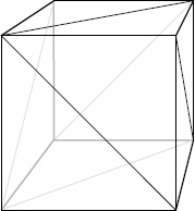
A cube consists of six
square faces and eight vertices. As each square needs to be rendered as
two triangles, we end up with a total of 12 triangles to draw, as shown
in Figure 1.
Because we will draw individual
triangles rather than use a triangle strip, we need to specify each
triangle coordinate individually. This means that when two triangles
share a single coordinate, we actually need to specify the coordinate
twice, once for each of the triangles. As a result, we have to provide a
total of 36 vertices, three for each triangle. Because there are only
eight distinct vertices forming the cube, this respecification of
vertices is quite wasteful and requires XNA to perform the same
calculations over and over again.
To build the vertices of the
cube, we simply declare an array of vertices and add to it sets of three
values, representing the vertices of each of the triangles. The
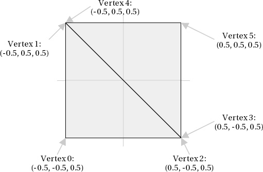
coordinates for the front face of a unit-size cube can be seen in Listing 1. Note that the z coordinate in each coordinate is 0.5, meaning that it extends half a unit toward the viewpoint.
Example 1. Defining the front face of a cube
// Create and initialize the vertices
        _vertices = new VertexPositionColor[6];

        // Set the vertex positions for a unit size cube.
        int i = 0;
        // Front face...
        _vertices[i++].Position = new Vector3(-0.5f, −0.5f, 0.5f);
        _vertices[i++].Position = new Vector3(-0.5f, 0.5f, 0.5f);
        _vertices[i++].Position = new Vector3(0.5f, −0.5f, 0.5f);
        _vertices[i++].Position = new Vector3(0.5f, −0.5f, 0.5f);
        _vertices[i++].Position = new Vector3(-0.5f, 0.5f, 0.5f);
        _vertices[i++].Position = new Vector3(0.5f, 0.5f, 0.5f);
|
Plotting out these coordinates shows that we have indeed formed a square that will form the front face of the cube, as shown in Figure 2.
The array is extended to cover all the faces of the cube, extending into
the 3D space by using positive and negative values for the z positions.
The full array is not included here because it is fairly large and not
particularly interesting, but it can be seen in full inside the CubeObject.BuildVertices function in the ColoredCubes
example project. The code in this function also sets the vertices for
each face to be a different color to make the cube look nicer.
|
The CubeObject class declares its array of vertices as static, so only a single instance of the array exists and is shared by all instances of the CubeObject
class. Because the contents of this array are identical for every class
instance, declaring the array in this way means that .NET allocates
memory for the vertices only once for the whole application instead of
once per cube object, saving some precious memory.
|
|
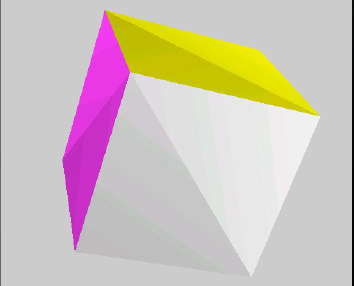
With all the vertices
defined, the object can be rendered using exactly the same code used for
flat objects. The result is shown in Figure 3.
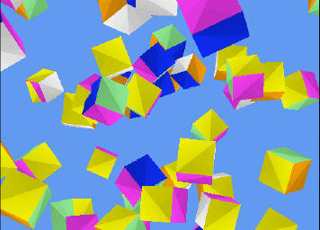
Fundamentally, that is all there is to it! If you run the ColoredCubes
example project, you will see how this basic object can be easily
reused within the game engine to create a much more visually exciting
scene, as shown in Figure 4.
This example creates 100 cubes, gives each a random angle and position,
and then rotates them around the y axis, resulting in a swirling
tornado of colored blocks.